

SmartThings compatible smart plugs are annoyingly expensive — typically around £40. This is far too expensive to consider buying many of. There are however WiFi plugs available online for around £10 that don’t officially work with SmartThings. Most of them are based on the ESP8266 chip which can be reflashed with new firmware that will work with SmartThings. Below I document my trials and tribulations with hacking these plugs
As of March-2018 I’ve tried 4 diferent makes of plugs with a variety of results.
Note — Regardless of the software you plan to use to flash the device, and regardless of the flash image you use, I recommend using pin headers (ideally soldered) to get a reliable connection during flashing. I got a pack for around £10 which has enough headers to do hundreds of smart plugs. I also recommend using a CH340G USB to serial adapter instead of an FTDI adapter as there can be issues with the drivers for the FTDI adapters. If you already got an FTDI adapter make sure you are using the older drivers. Also ensure your adapter can supply 3.3v rather than 5v (which will likely fry the ESP8266 chip)
I have used Sonoff-Tasmota which I build and install via the Arduino IDE (see bottom of post for additional info). I then installed a custom device handler, made by Brett Sheleski.
By the end of my experiments I had 2 working SmartPlugs, having bought 4 different plugs (£44.94 total), 1 USB adapter (£5.99), and 1 set of pin headers (£6.69). If you don’t have a soldering iron you’ll need one of those too (£26.29). Including the soldering iron my total cost was £83.91. Had all 4 plugs worked this would have been decent value. As it is, I’ve got 2 working plugs, at a cost of £41.96 each. This is almost identical to a Belkin WeeMo, which might make the whole thing seem pointless — and if you only want a total of 1 or 2 plugs it probably isn’t the best way to go. However, I plan to have quite a few more plugs, and I can now add more plugs to my collection at a total cost of £8.97 each as I already have everything else I need to flash them. (Update Dec-2018, I now have a total of 20 smartplugs, and have paid no more than £12 for any of them)
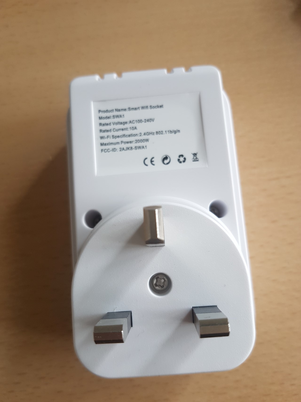
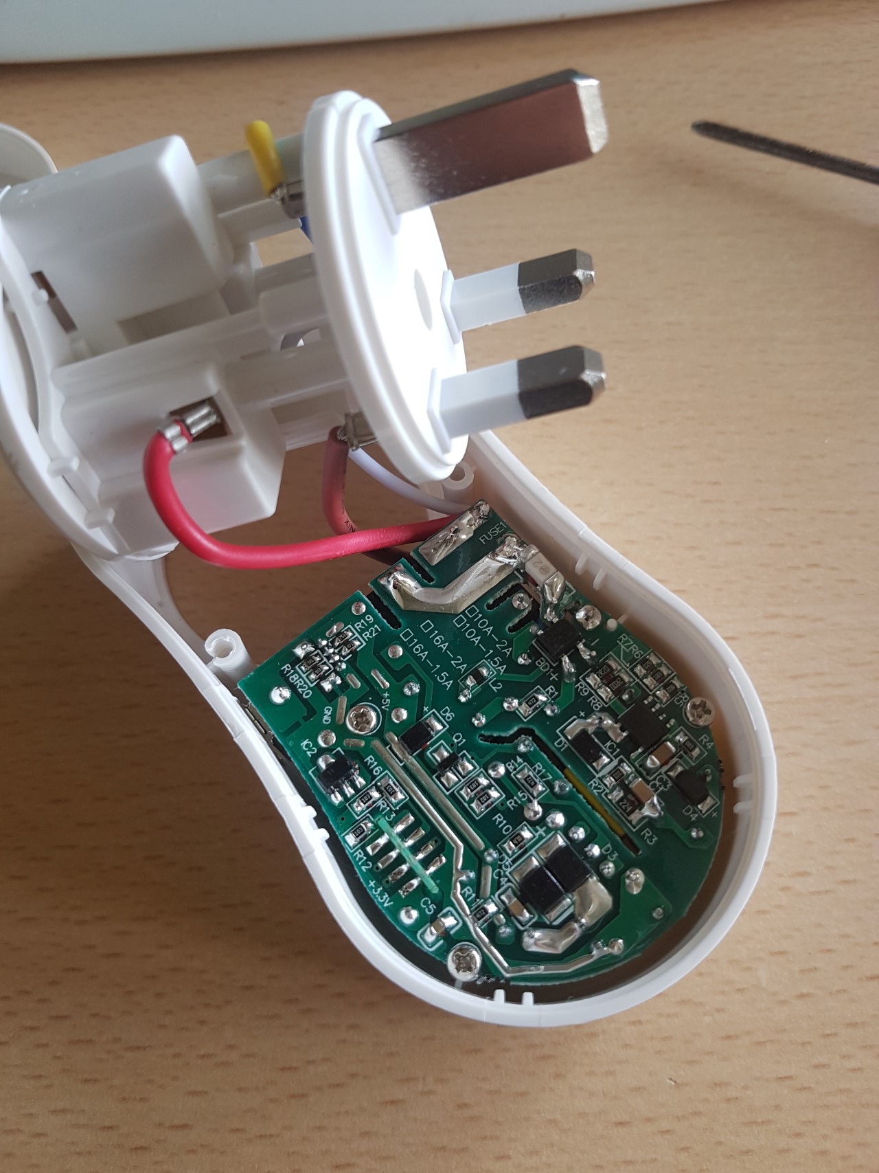
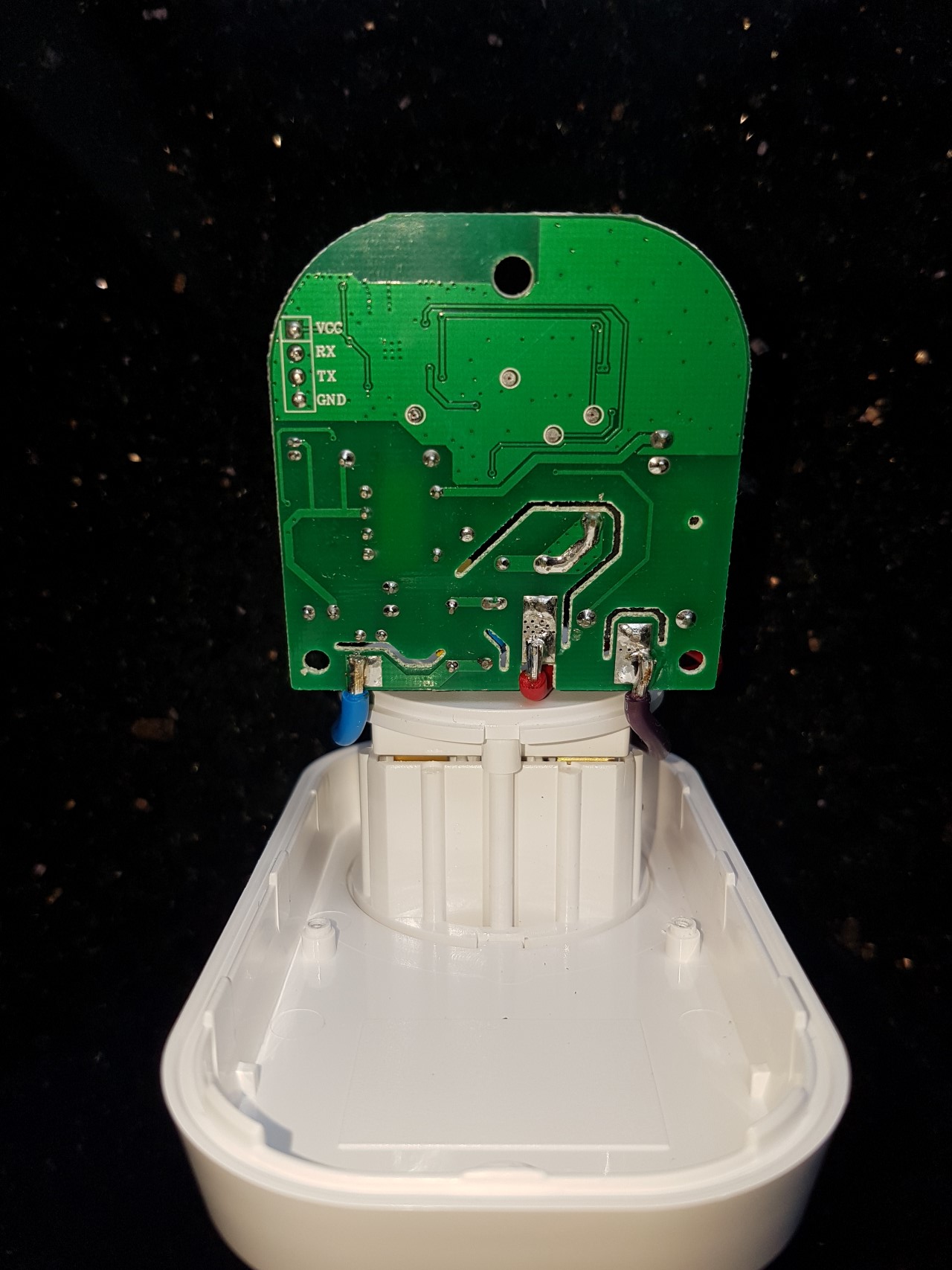
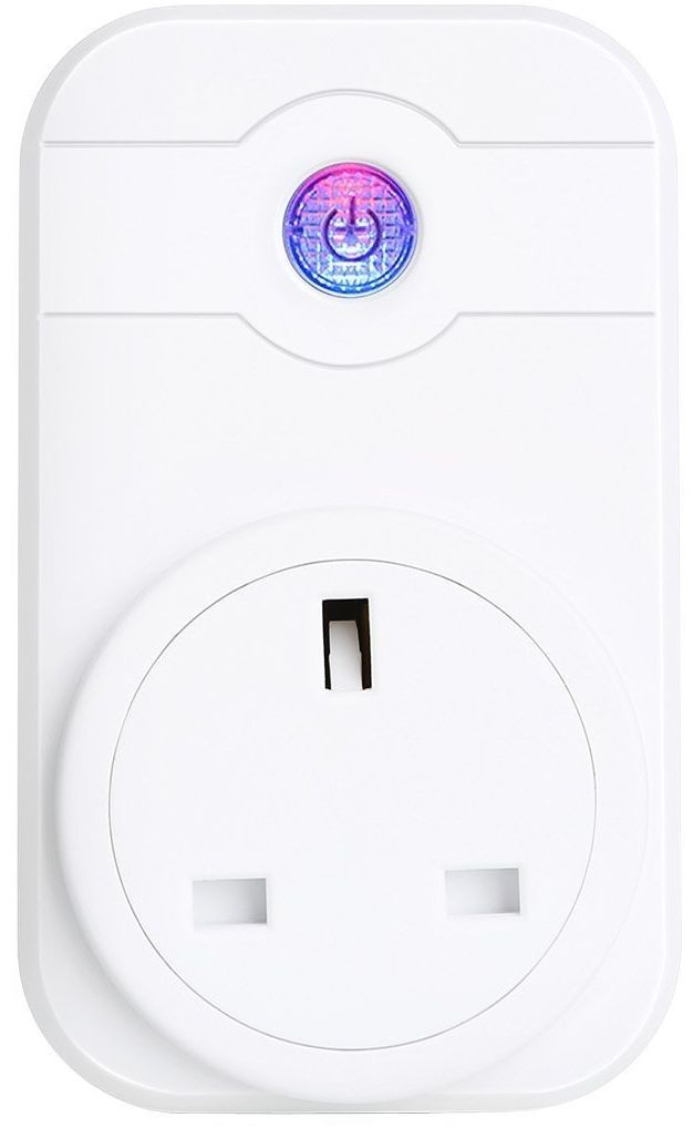 1. SWA1 (has a purple button) — branded as COOSA, Annstory, Linganzh, and no doubt other names too. Seems to be associated with the app “eFamilyCloud”.
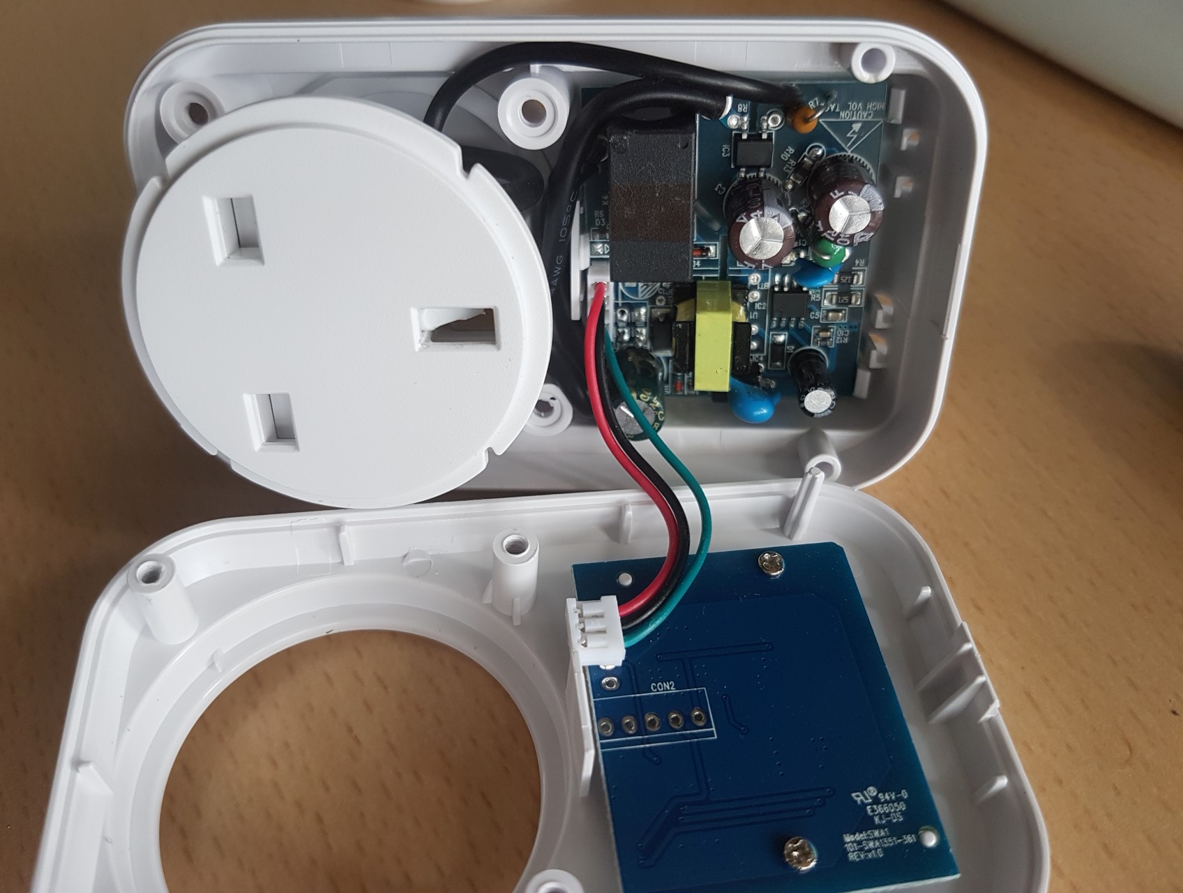
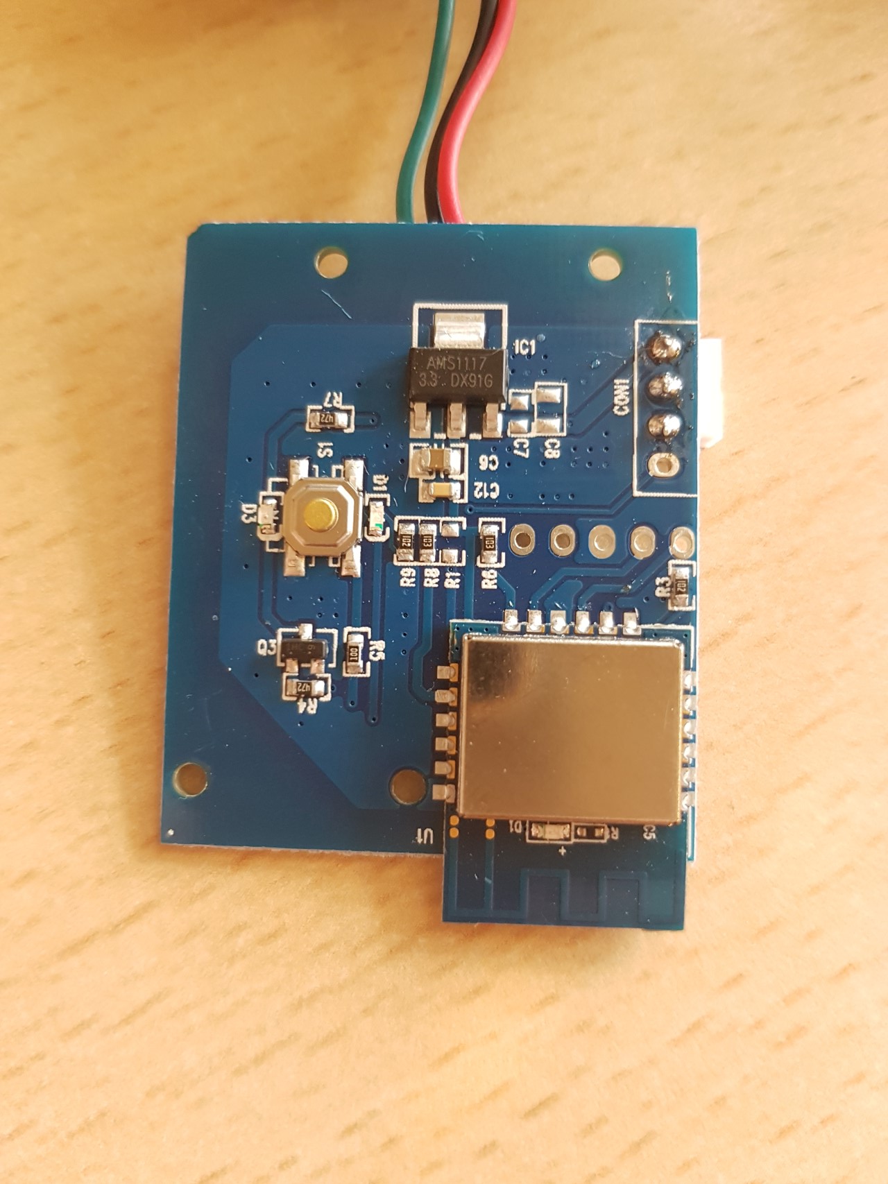
This has a second PCB inside it which is labelled as an SWA1. Googling this indicates that it uses an ESP8266 inside and a successful firmware hack has been documented (with pins shown) by Nathan Chantrell. I have followed Nathan’s method with success, although the module type didn’t show up the first time (I made an error modifying the code) but I was able to get the device working by selecting Generic and then configuring the pins myself. This worked but not quite flawlessly, so after a bit of reading I reflashed it. Nathan’s guide doesn’t make it clear that 3 changes are needed to the code before flashing — the large section at the bottom, and the matching name from it needs to be added to 2 lists above which should be obvious when viewing the file. Since reflashing (via the web interface) it has worked very well. To keep the soldering simple I fed 5v from my USB adapter to the 5v pin, but I left the adapter set to 3.3v (i.e. the setting for the data pins). So it is worth having an adapter with both 5v and 3.3v pins and a jumper to set the voltage of the data pins independently (as the CH340G I linked to on Amazon has). I was able to leave the pins attached by bending them over to nearly 90degrees before putting the PCB back into the plastic casing.
_
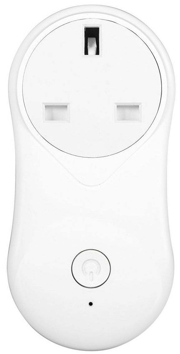
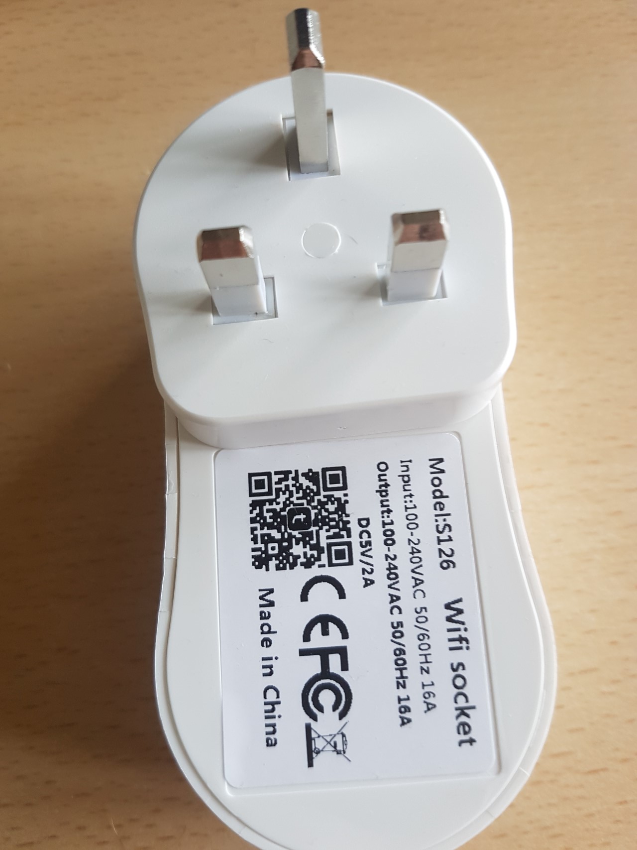
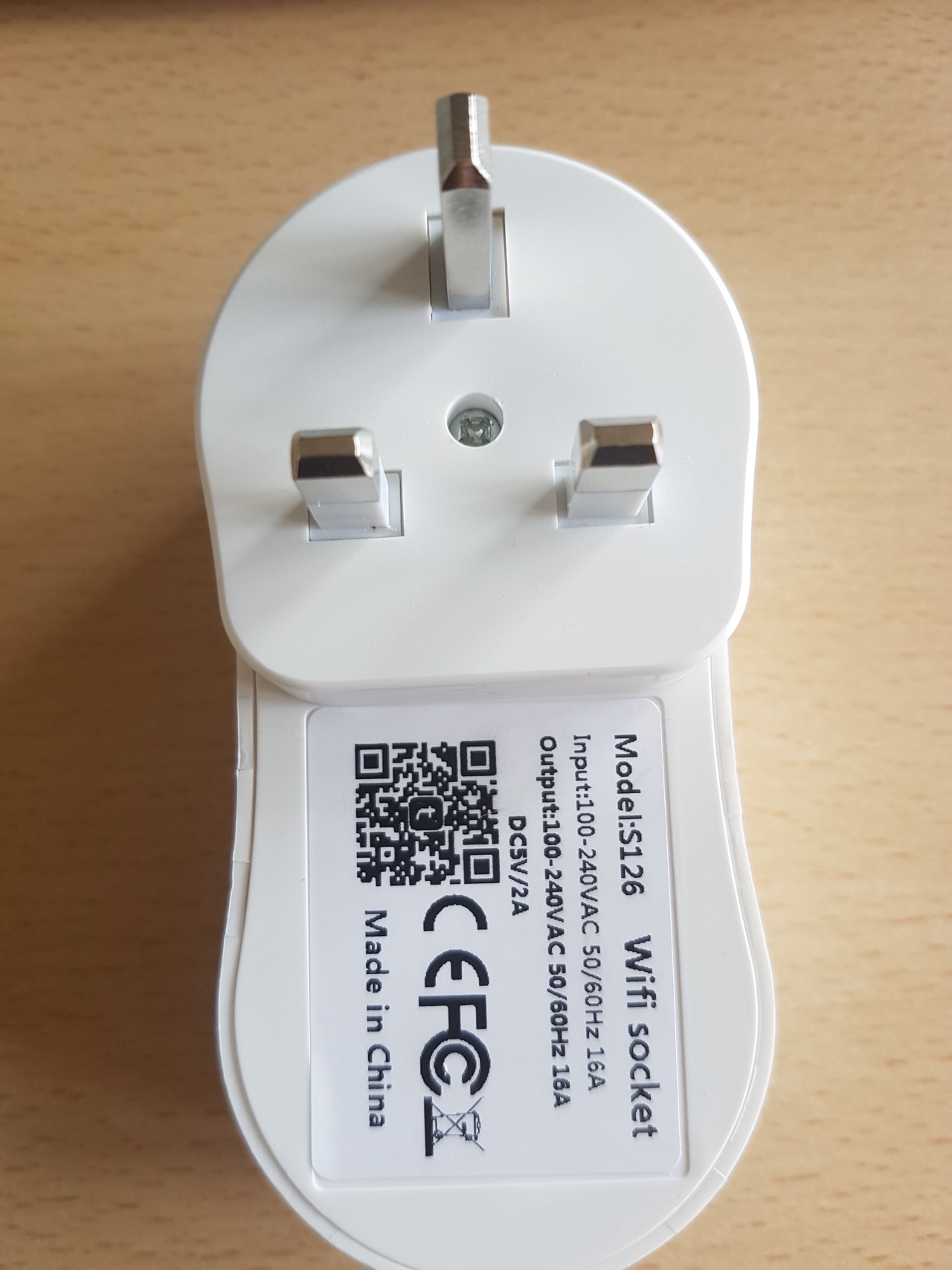
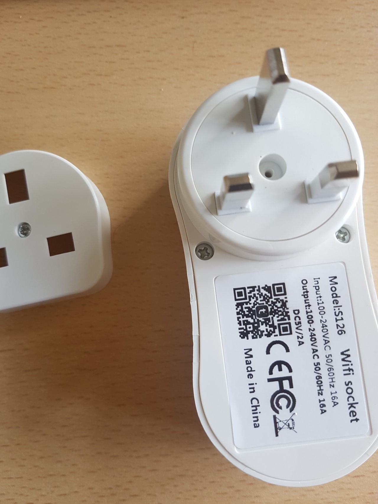
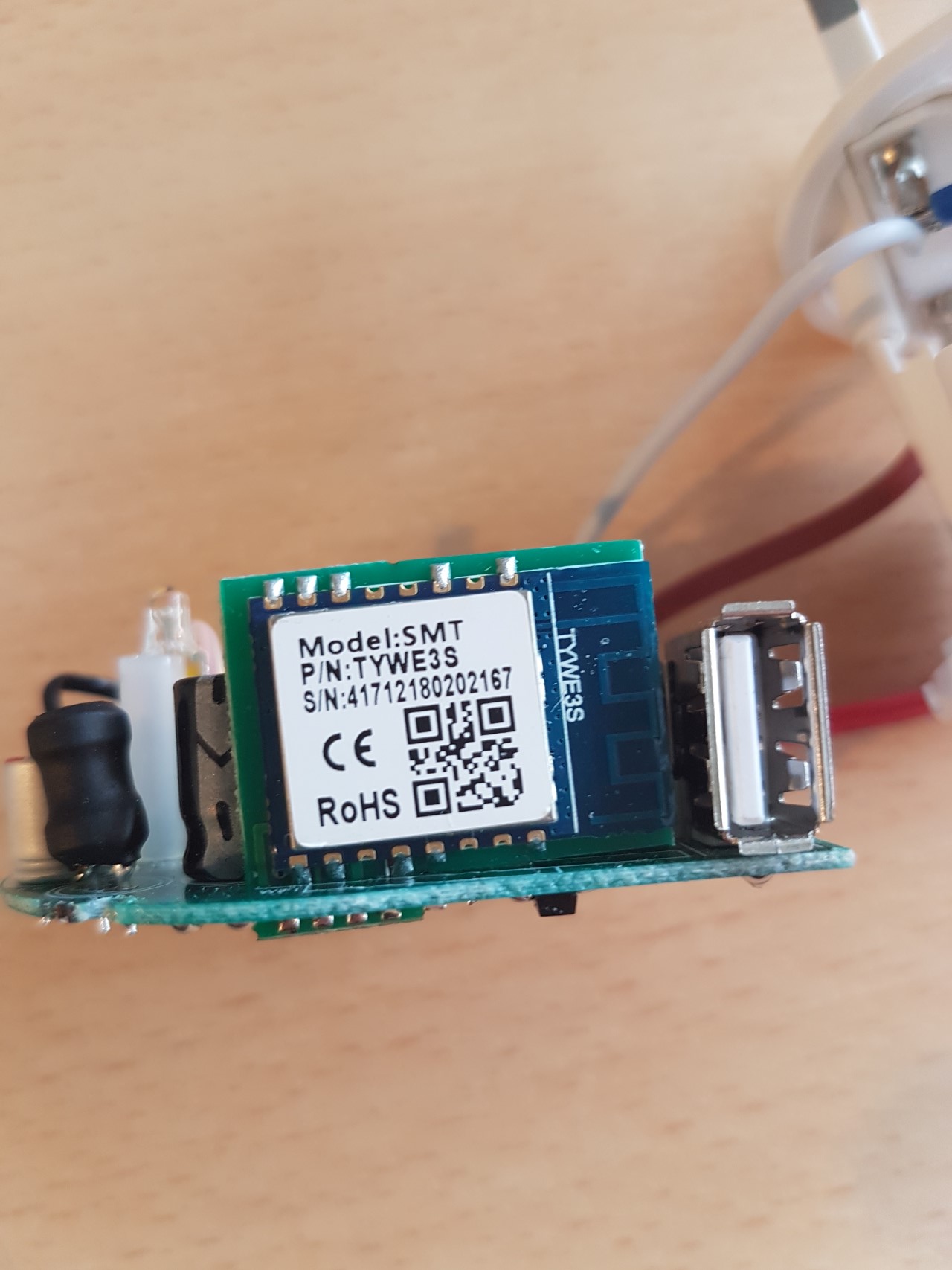
2. The HowiseAcc S126 Smart plug with USB (curves in slightly in the middle)
Information online indicated that the TYWE3S component in this smart plug contains and ESP8266 and hence it should (in theory) be flashable. I have not as yet identified the correct pins, altho there are labels for 3.3v and ground on the underside and the TX, RX and GPIO0 pins on the TYWE3S are shown on a similar device on a post on GitHub. I found at least 1 other thread with another person asking about the same device, and some more information from Andreas Engel, but with 2 of my 4 “test plugs” working I decided that trying to solder this headers on this plug was too difficult and have ditched it. If you’ve got a steadier hand than me then take a look at the link, especially the second one and please let me know if you have any luck.
_
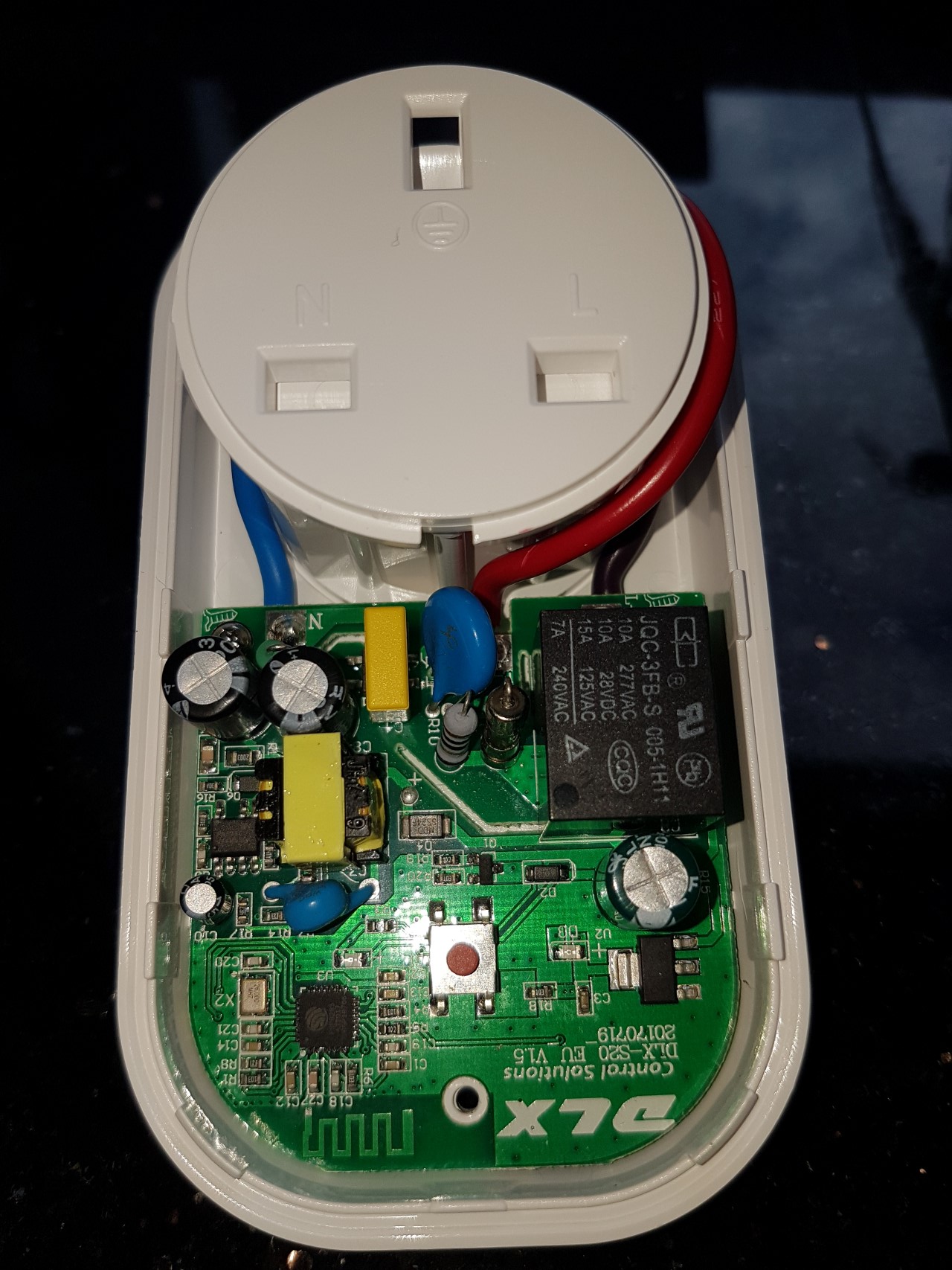
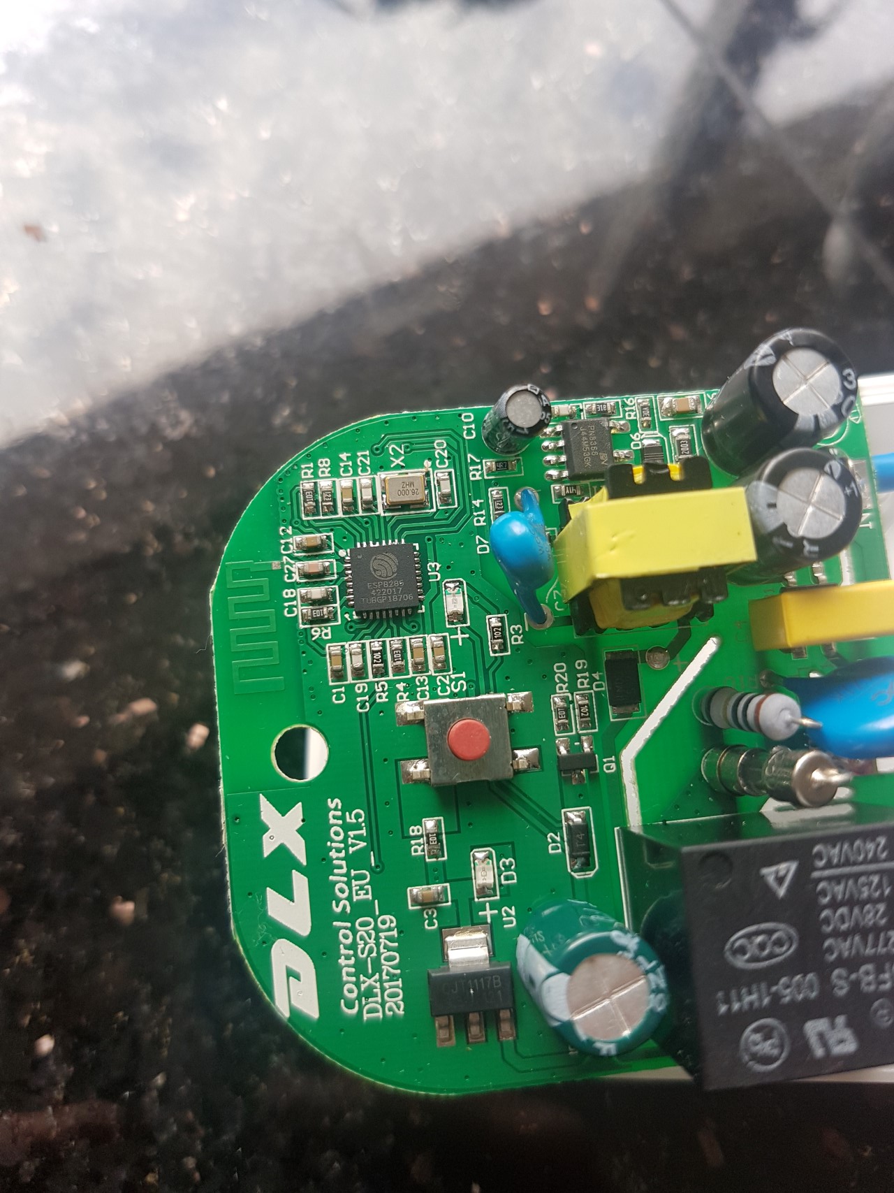
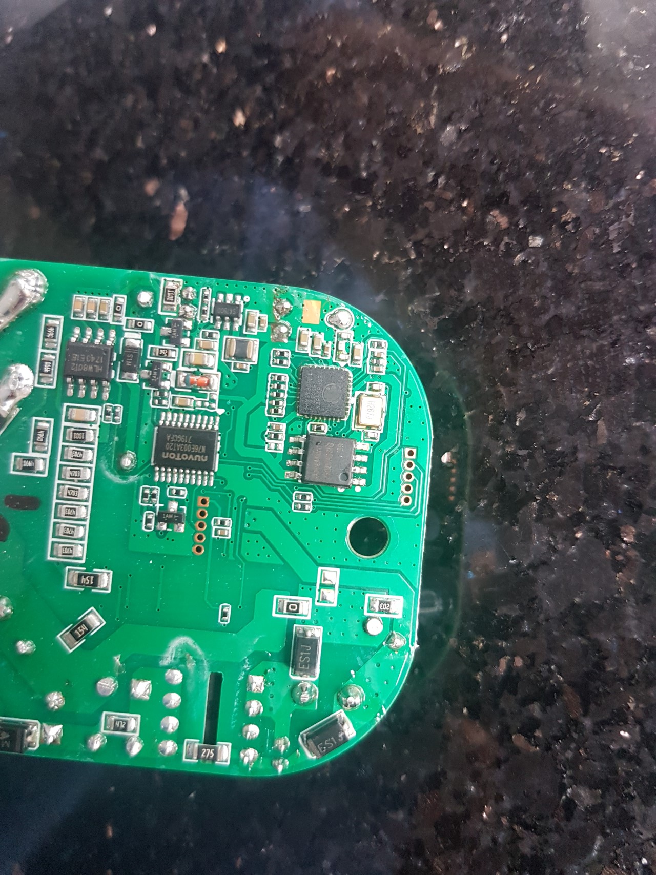
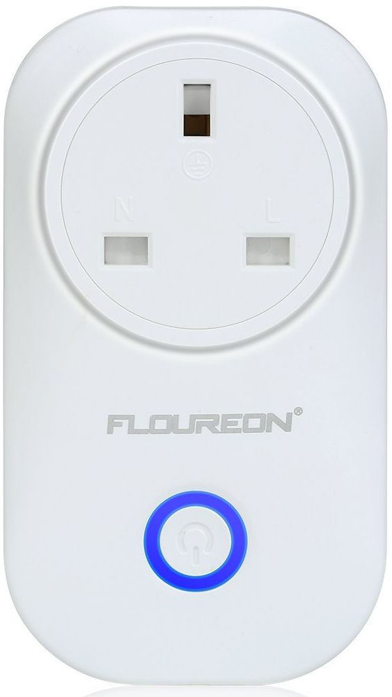 3. Floureon PS-16-MB Smart Plug
This has an ESP8285 chip onboard which is compatible with the ESP8266. It has trickier headers to solder but once soldered it flashed perfectly first time. Just connect the 4 regular pins (3.3v, ground, TX, RX) and hold the button down whilst powering it up (1−2 seconds was enough). As this is effectively a Sonoff S20 clone I suspect it can be flashed more easily with the NodeMCU flasher by following Eric M’s guide, S20 firmware, Device handler, and Smart App code. However, I preferred to go with the Tasmota firmware as I had already set everything up to build and flash it, and it supports the other smart plugs which aren’t all Sonoff S20 clones. The choice of which way to go is up to you.
_
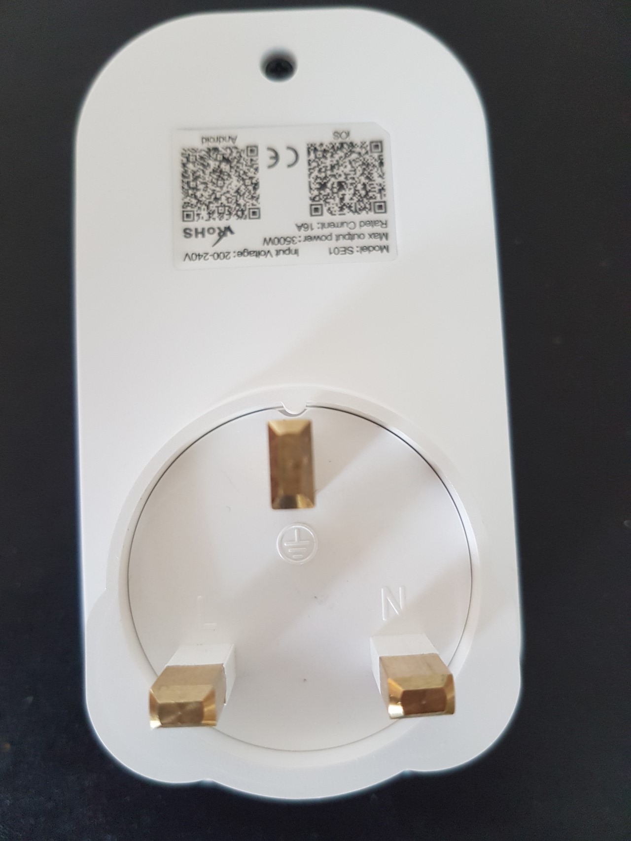
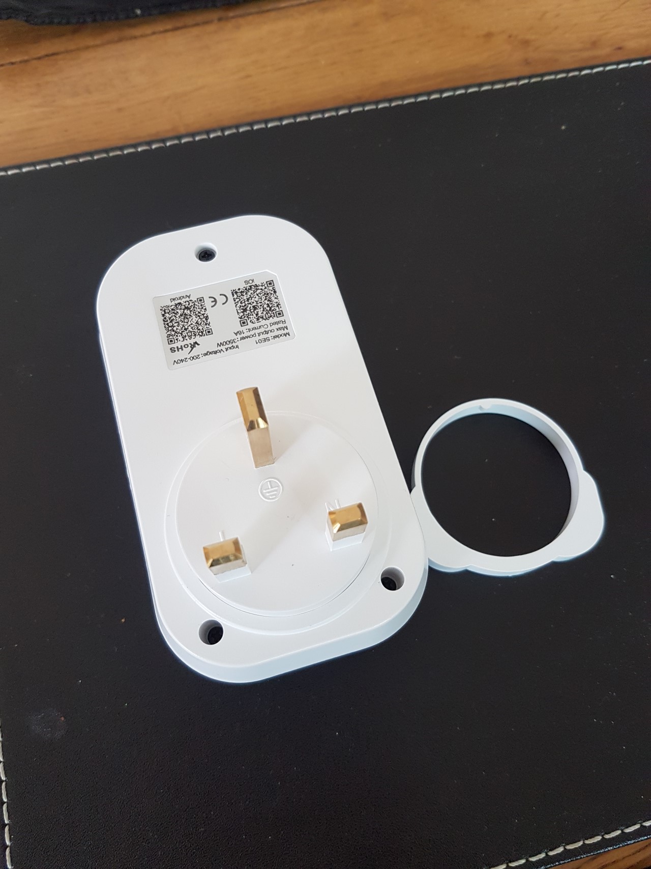
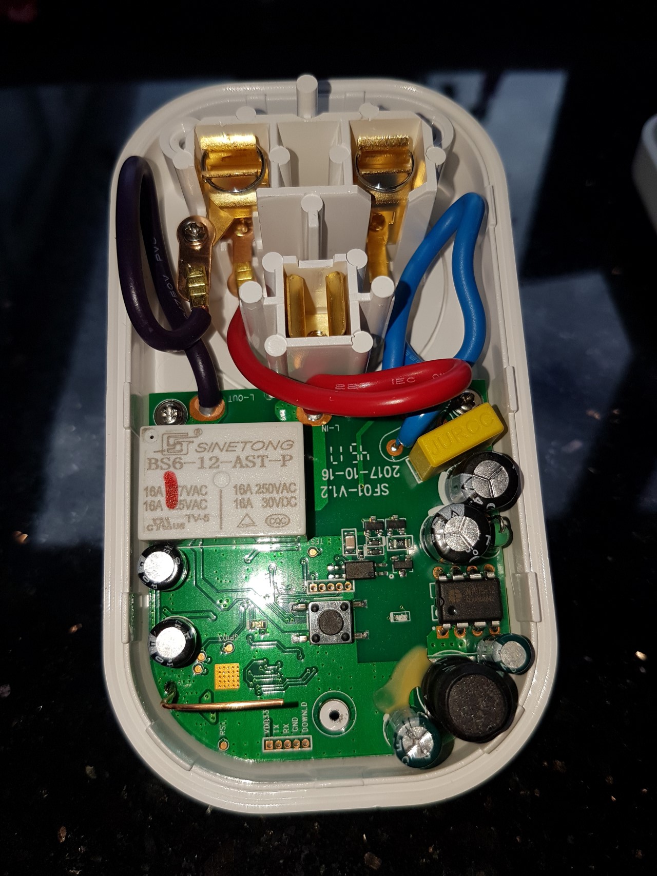
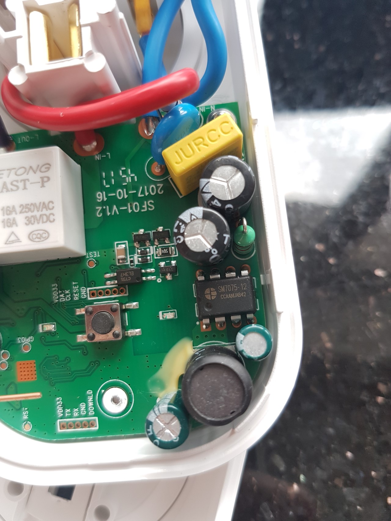
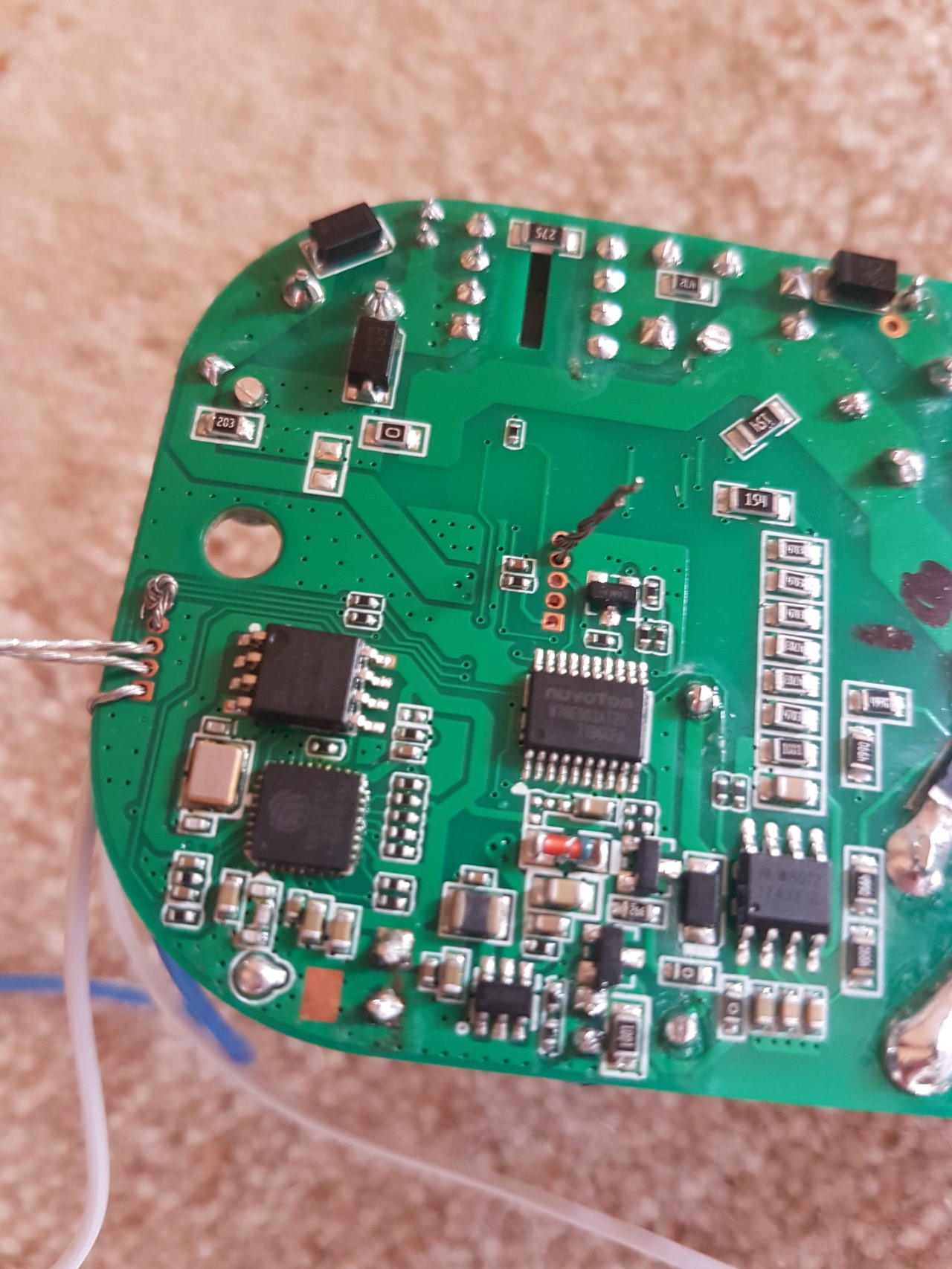
 4. The Aonokoy SE01 (16 Amp) smart plug
This has an ESP8266 and easy to access headers, although they are too close together to connect regular pin headers to so I used loose wires instead. I have been able to connect mine to my PC and flash it. After flashing it boots up as expected and the web interface of the firmware loads, but the unit crashes after around 10 seconds every time. I am not sure why this is, but it does it with several different firmwares flashed onto it. I am hoping it is just bad luck with a duff unit.
_
5. The Hyleton HLT 315 smart plug (looks a lot like a Floureon on the outside)
This was more fiddly than I had hoped as there are no pin headers on the PCB itself — instead you have to solder to the existing join between the main PCB and the wifi card PCB. Fortunately there was a guide for a very similar 313 device which (correctly!) identified the pins needed. Flashing was successful and the only difficult part was to identify which device type to select (or customise) so that the LED, button, and relay would all work. The GPI0 pin had to be shorted to ground physically, as holding the button down didn’t put the device into flash mode. This was a bit fiddly — I really needed 3 hands! It is possible to (mostly) configure the device correctly by using the generic device type and setting GPIO2 as Led1i, GPIO13 as Button1 and GPIO15 as Relay1. If you also want the red LED to be always on then set GPIO0 as Led2i.
Building sonoff-tasmota yourself
- Download the Arduino development environment
- Install and run it
- Open Preferences from the File menu
- In “additional boards manager” enter
https://arduino.esp8266.com/stable/package_esp8266com_index.jsonand click OK - Open Tools > Board > Boards Manager
- Search for ESP8266
- Hover over the result and click the
Installbutton that appears - After it has installed change your board using Tools > Board >and select the
Generic ESP8266 Module - Close Arduio IDE
- Install the drivers for the CH340G (download theme here)
- Download and extract from zip the Sonoff-Tasmota firmware
- Open sonoff.ino in the sonoff subfolder (this will reload the arduino IDE)
- Optional: Edit 2 lines (lines 62 and 63) in my_user_config.h to set wireless network name and password
- Connect the CH340G to the board, and then plug the CH340G into a USB port
- Select Upload from the Sketch menu of the Arudio IDE
I found that with newer builds of Sonoff-Tasmota that at least 1 LED would flicker continuously. I eventually realised (by looking at the logs) that this was because MQTT is enabled by default and the device is searching continuously for an MQTT network / controller or something. I don’t use MQTT so I turned this off and the LED stopped flashing.
Jon, I have a number of the SWA1’s that I’d like to flash however I am stuck at customizing the firmware to include the SWA1 before flashing. Nathans site shows the edits to make, however the firmware downloads all appear to be bin files, so I’m not sure how to access the sonoff_template.h file?
how did you manage to flash this Aonokoy device?
There are some guys trying to flash it but its not possible…
I used the CH340G USB adaptor linked at the top of the article, and just stripped the wires and poked them through the holes in the PCB. That wasn’t easy as they always want to twist and touch each other, or they want to lose contact. You can see how the wires are looped through in the 5th image (https://diymediahome.org/wp-content/uploads/aonokoy_6.jpg). There are 2 areas that need wires connecting — the set of 5 holes near the edge of the PCB which need 4 wires from the USB adaptor. The last 2 holes need connecting together. There is also another set of pin holes near the middle of the PCB — 2 of these need shorting together. I then used the Arduino IDE to flash Sonoff Tasmota as described at the top of the article. As I say above altho it worked, it crashes after a short period